
CAD / DIGITAL DESIGN
Define the target shape, dimensions and key features as the development reference.
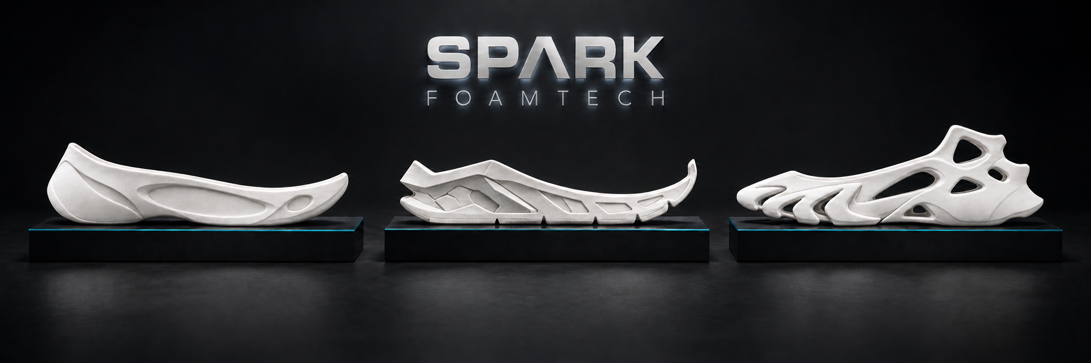
Efficient production, technical performance and sculptural design. Three approaches for different product priorities.
Three stages explain the basic transformation: define the design, create the smaller GEB preform, then expand it through foaming.
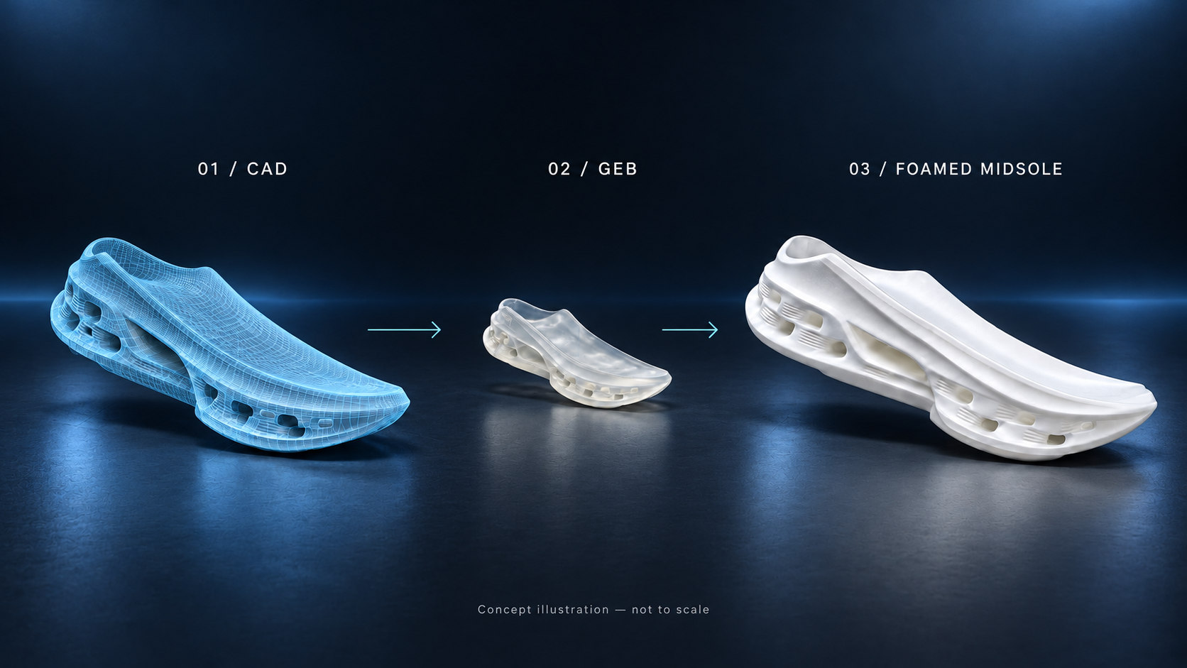
Define the target shape, dimensions and key features as the development reference.
Translate the design into a smaller preform. Its geometry is adjusted for the selected material and expected foaming behavior.
Foaming expands the preform into a foam structure. Check the resulting shape and dimensions against the design target.
Concept illustration, not to scale. GEB development involves material-specific adjustments, not simply uniform CAD scaling. Actual expansion and any subsequent forming or finishing depend on the project; CM SCF includes secondary compression molding.
For Direct Forming and OneTime Forming, the GEB carries the complete design before foaming. The intended shape and details must be developed into the preform, with its geometry matched to the material’s foaming behavior.
Overall form and proportions
Sidewalls, openings and three-dimensional features
Surface patterns and intended design details
These features are developed into the GEB within the selected route’s capabilities. Foaming expands the preform; the GEB design and material behavior must work together to achieve the intended result.
Develop complex sidewalls, openings and sculptural features into the GEB. Tooling and foaming development focus on preserving the defining design intent.
Develop production-friendly shapes into the GEB, using validated materials with predictable foaming behavior to support efficient volume production.
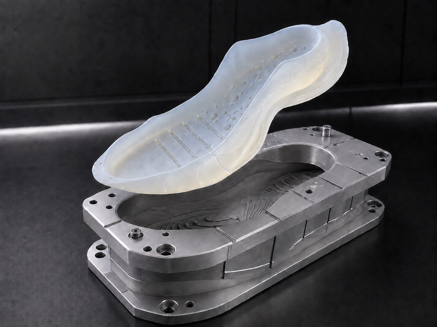
A second compression-molding stage provides a further opportunity to refine dimensions, shape and surface details after foaming.
Direct Forming and OneTime Forming rely on the GEB to carry the design, without a secondary compression mold to correct it after foaming. Their design scope, material selection and development requirements remain different.
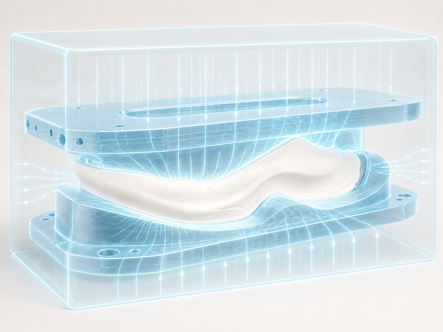
A foamed preform is refined in a second compression-molding stage to improve shape, dimensional control and surface definition, supporting a broader range of materials and properties.
Concept illustration; not an actual mold specification or process parameter map.
Compare material ranges by rebound, hardness and density. KINETIC FOAM is now labeled CM SCF; other material-family names remain as supplied.
| Product requirement | OneTime Forming | CM SCF | Direct Forming |
|---|
Application ranges may overlap. Similar shapes can call for different approaches when materials, performance or finish requirements differ.
Share drawings, sidewall height, openings and essential 3D features.
Define performance, finish, dimensions, target unit cost and volume needs.
Evaluate the approach by project; develop and accept against agreed tests, samples and specifications.